|
|
|
The Woodcrafter Page© 2004 - all rights reserved.
|
|
|
|
Here is the orginal article from the
January - February 1956 Deltagram
ROCKWELL MANUFACTURING COMPANY - A DELTACRAFT PULICATION
|
Double Sided Bookcase
|
|
|

|
| |
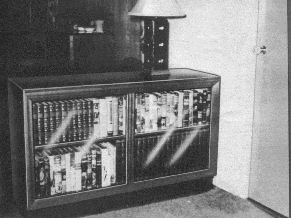
This practical case could serve several purposes in the home. It makes an ideal room divider as shown in the above photo. It could also be used in the boy's or girls' room where two children must do their studying. Each would have their own private shelf space.
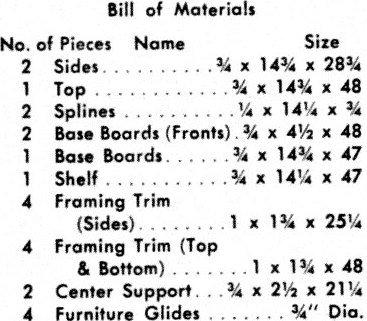
The entire case can be made of ¾ inch plywood except for the framing trim and center supports which are made of solid stock. For a neat job, the sides and tops are mitered and held together with ¼ x ¾ inch splines, (see detail Fig. 3). The front base boards are rabbet cut to fit against the sides (Fig. 6). Making the joint in this manner leaves only a 1/16 inch exposed edge. The shelf can be assembled permanently to the sides by fitting into a dado groove, (Fig. 1), or made adjustable by means of a series of holes bored into the sides to
|
take conventional shelf supported (Fig. 2) .
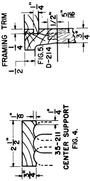
Front trim on both fronts of the cabinet is made of l x 1¾ inch stock. The front face is moulded on the spindle shaper with the D-214 cutter as shown in Fig. 5 and Photo #4. Center trim is made of ¾ x 2½ inch material with the face moulded by making three passes over the 35-211 cutters on the circular saw, (Fig. #4 and Photo #3). The ends are fitted into the front trim with a 5/16 x ½ inch long tenon, (see drawing Fig. 5).
Sand project thoroughly making sure to break all sharp corners. Stain to match present wood trim in room. Apply two thin coats of white shellac followed with a coat of rubbed effect varnish. For easier moving of case, use ¾ inch furniture glides. |
|

Photo #2
By using the taper jig on the circular saw, you can cut two legs at one time if the stock is ripped to ¾ inches wide.

Photo #3
After taper cutting the legs, they are bevel cut by setting the straight edge of legs against the miter gauge body that has been set at 80°.

Photo #4
Dowel holes are bored on the drill press with the 5/ I6 inch machine spur bit fitted in the router spindle. Note these holes are bored only part way, see drawing Fig. 4.
|
| |
|
Right-click here to download the drawing as an Adobe Acrobat (pdf) file.
* * * * Click on the drawings above to download a higher resolution picture. * * * *
*********** WARNING***********
Read my page on safety before building this item.
|


