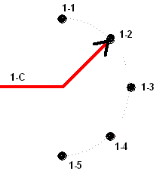
The schematic (drawing 14) for a rotary switch looks much like is physical layout. The common terminal may be marked A, A-C (for circuit A common), 1-C (for circuit #1 common), or some similar manner. The individual position contacts will be marked A-1 (for circuit A - position 1), 1-1 (for circuit 1 - position 1), or similar. The most common method is 1-C (for circuit #1 common), 1-1 (for circuit 1 - position 1), 1-2 (for circuit 1 - position 2), 1-3 (for circuit 1 - position 3) …... Diagram 14 shows this method. 1-C is the pole (common contact) and the others are the switched contacts 1-5.
The dashed curved line through the contacts indicates the 'swing' of the pole. |

Diagram 14 |