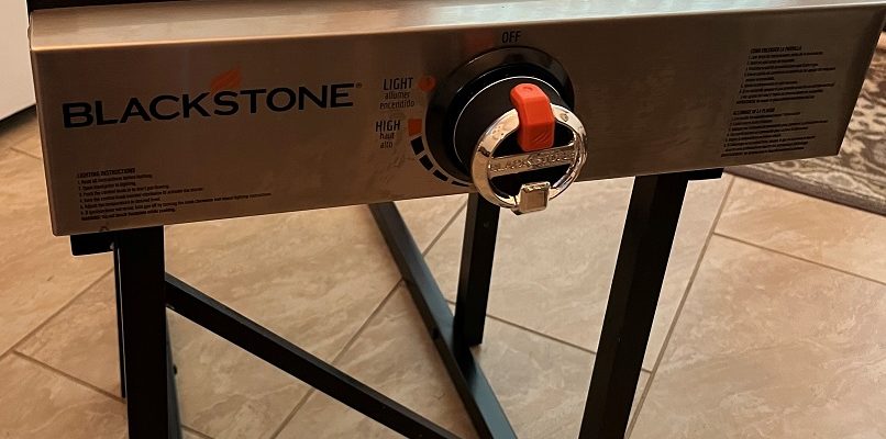
Hack #44 Outside rack for your 17″ Blackstone Griddle.
FYI – This post is specifically for the Grand Design 22MLE trailer but should work on most others (including other brands) – but may need changes in measurements.
I have heard soooo many people carry on about how great their Blackstone griddle is but I insisted on sticking with my Weber grill – for the longest time. How could I know what I might be missing here?
I used our friends’ Blackstone several times during our last trip so I was sold! I am now the owner of a 17” Blackstone griddle and would recommend it to anyone out there.
I truly am amazed at how much better it cooks everything and how so very easy it is to clean up afterwards.
My friend’s RV has an outdoor kitchen which makes cooking outside a far better experience and got me thinking – again. I originally had a rear-bumper mount for my Weber grill but did not like being banished to the rear of the RV to use it. I’ve previously contemplated some rack/bracket to attach my Weber grill to the side of the RV but did not want the heat too close. However, the Blackstone does NOT generate any significant heat to the back of it. I cooked on it using a camp table first and stood behind it – less than 10 inches from the back. It was simply warm – not at all hot. The final unit positions it far enough away I can feel only a minute warming of the trailer surface from the hot griddle.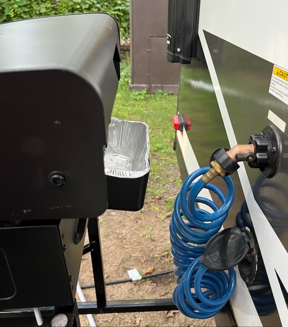
I engineered a bracket for it on our MLE and love it. It could be mounted on ANY RV, not just the MLE. Basically, it is designed on the idea of a 1″ square metal channel that slides into a larger channel – much like how your hitch slides into the receiver on your tow vehicle.
Supplies:
You need one 3′ length of 1-1/4” square steel channel, two 3′ lengths of 1” square steel channel, three 3′ lengths of 1” square aluminum channel, one 3’ length of 1” aluminum ‘L’, three 3’ lengths of bracing , four ¼” insert nuts, Four 2” long ¼” wing bolts, four ¼” locking nuts, rivets, and two U bolts (wide enough for the 1-1/4” channel). These are all available at both Lowes and HD.
Notes:
Anywhere two pieces of channel meet end-to-end, bolt them together internally using short bolts (1/2” long is good). Drilling the holes requires very careful and exact locations to ensure they line up once they are bolted together. You can also add a drop or two of super glue here to add to the stability. A drop of super glue (or nail polish) on the bolts and nuts will also serve to prevent loosening later.
To see a larger version of any pic, simply RIGHT-Click on it and select Open in a new tab/window.
The Receivers
The first part is the permanent receiver mounted to the frame under the RV. Simply cut a 3′ length of 1¼” square steel channel into two 18″ lengths. These are bolted to the frame, under the RV, using U bolts. You do have to drill holes (precisely) for the U bolts. Be sure to spray the holes with a good primer and let it dry well before inserting the U bolts to prevent a point for rust to start.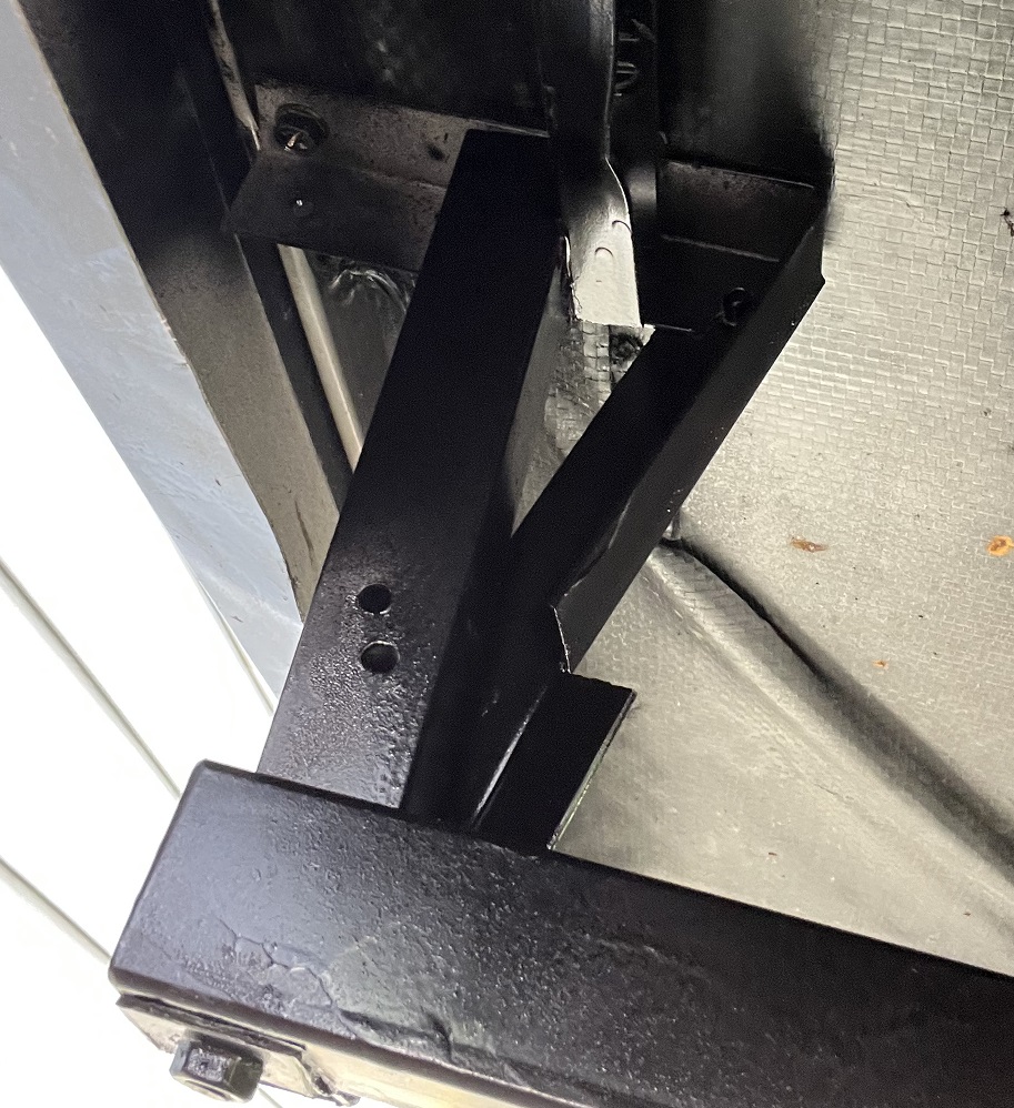

I also added a structure to allow it to be fastened to the under belly near the edge of the RV. The unit was rather sturdy and strong without this but ALL movement was eliminated.
For each vertical support, cut a 7½” long piece of 1” square aluminum channel. Bolt it together to the steel channel vertically at a 90 degree angle.
At this point the inside hole is too small for the smaller channel to slide in. Place the larger piece into a clamp then use a metal file to file down the head of the screw until the smaller steel channel just fits inside.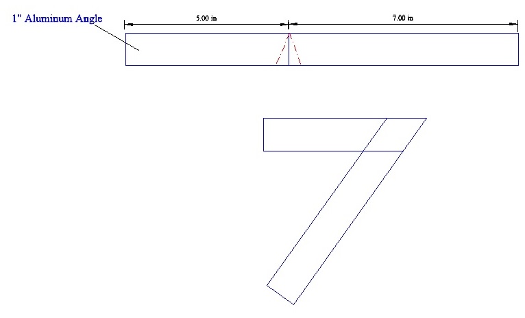
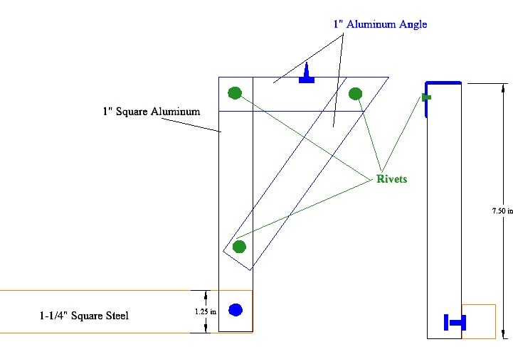
Now. cut a 12” length of 1” Aluminum ‘L’ stock. Mark a line 5” from one end. Cut a ‘V’ notch into one side here. The angle cut should be about 115 degrees. If you want symmetry in these pieces, take care to observe which way you turn and cut these (but not critical since they will be out of sight). Drill a hole into the top of the short leg close to the end. This is where you will screw it to the RV. Drill the proper size holes into the side of each end, where it will mount to the square channel, for the large rivets you will be using. Bend it to a right angle for now (it will be bent more later) and attach it to the top of the vertical square channel, at a 90 degree angle, with a large rivet
Do NOT mount these until everything is built. Set them aside for now.
Next are the two side brackets that make up the rack.
The rest is made primarily from 1” channel. You need the remaining two 3’ long pieces of steel channel for the ‘slides’ that fit into the receivers. Cut the 1” aluminum channel into two pieces 12” long and four pieces 18” long. These are the sides and tops. Note: you can make the vertical pieces less than 18″ if you want the final unit lower. I am over 6′ tall and this is the height I like but it is fairly high. 15″ would work fine.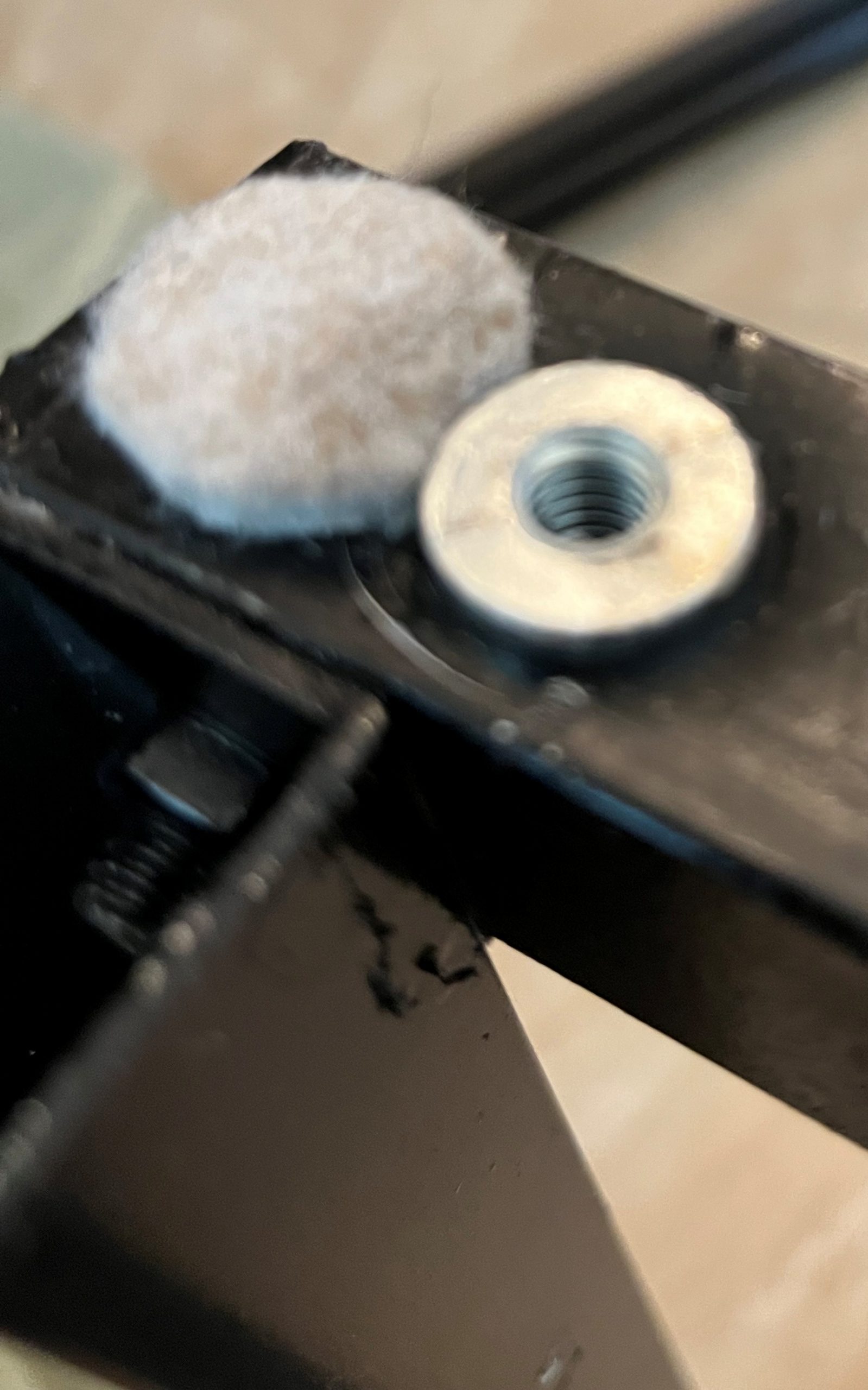
Remove the legs from the base of your Blackstone. Carefully, and precisely, locate and drill holes into the top of each 12” length to align precisely with holes in the Blackstone base. The positioning of the insert nuts is CRITICAL to ensure that the base mounts easily to the system later. Drive in the insert nuts.
I
Bolt each of these to the ‘inside’ of the 12″ length and ‘outside’ of the steel channel to form a rectangle on the end of each one. The steel channels will both be toward the center. Use short bolts (keeping inside the channel) on the three location that are both open ends and a 1-1/4 length bolt where the channel bolts on near the center of the steel channel.
I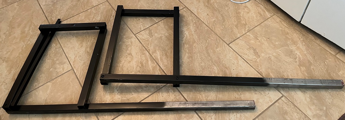
Cut two pieces of the bracing 16” long and two pieces 10” long.
(Pics coming soon.)
Attach the 10” long braces to the inner side of each side rack with small rivets to create supporting triangles. This will ensure the sides remain square.
(Pics coming soon.)
Attach the 16” length to the front of one piece. The other end will be secured later. This is the front support.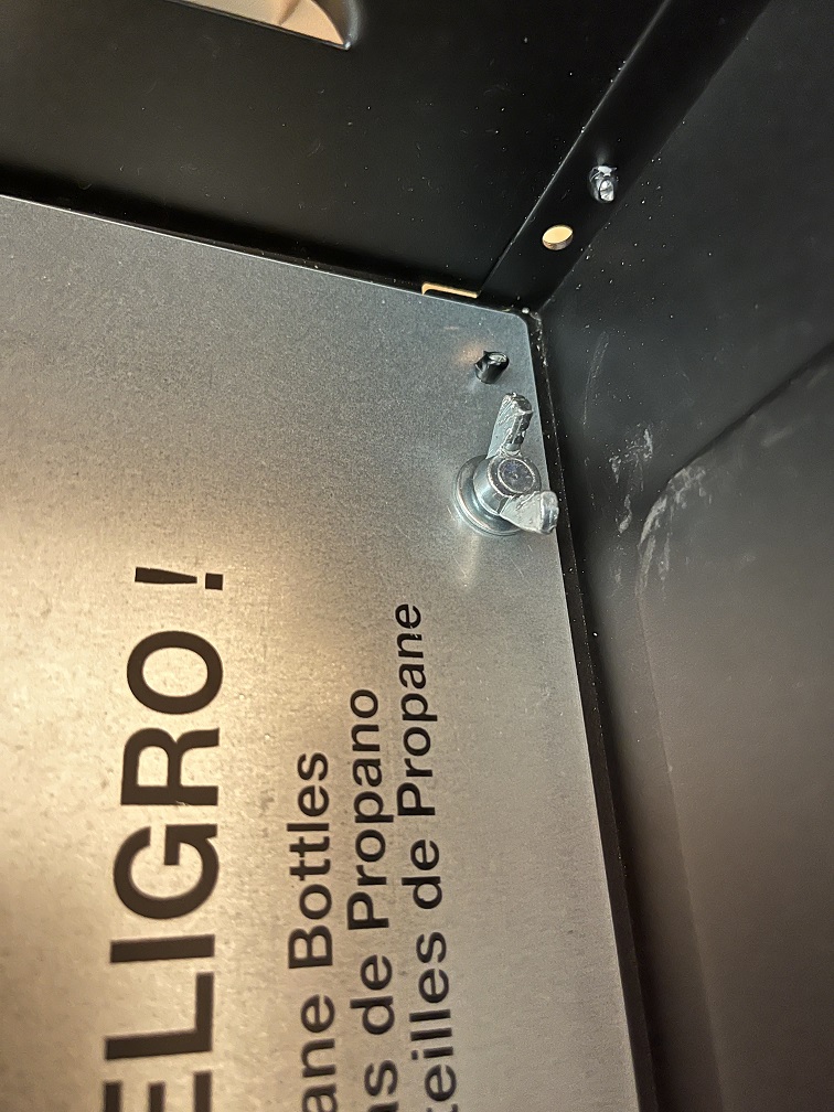
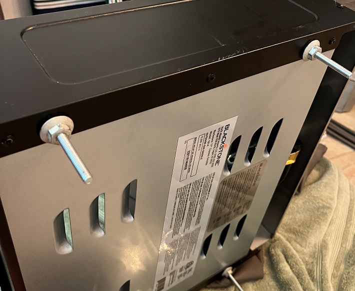
Install the 4 wing bolts through washers then the holes where the legs were. Add washers and the LOCKING nuts to secure them to the base but do not tighten them tightly. Allow just enough freedom that you can easily turn them with the wings. Note: I changed mine to hex head bolts and have a socket I use on my cordless drill for them since the space for turning wing nuts is so tight.
Mounting the permanent supports.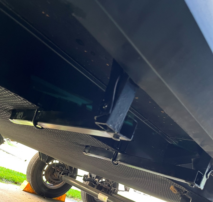
Drill holes for the first U bolt. Be sure to spray the holes with a good primer and let it dry well before inserting the U bolts. Bolt one of the receiver pieces to the frame (loosely) so that the forward edge of the brace is located at the edge of the underbelly. This needs to be screwed into solid material. Once the assembly is in position, tighten the U-bolt. Now, drill a pilot hole and screw the front brace into the underbelly. You will need to ‘flex’ the thin skirting out of your way (best done by a helper).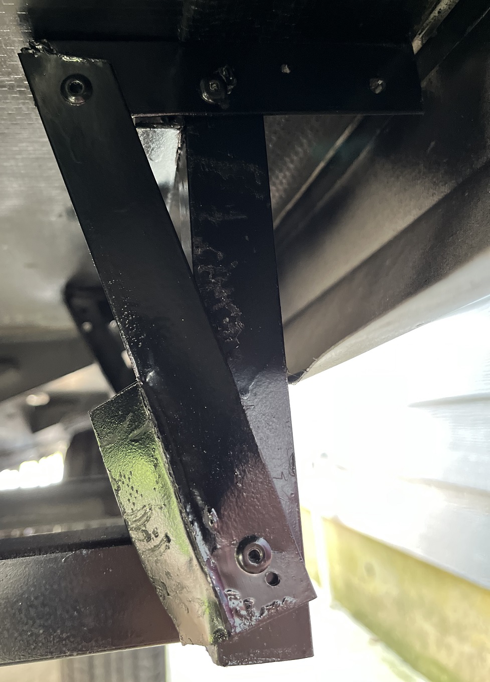
Bend the bracket down and drill and rivet the other end to the vertical channel. Drill and rivet through the side near the bend to help hold it in shape.
Measure the distance between the two rear wing bolts you mounted to the base (center-to-center). Subtract 3 inches from this. This is the distance the remaining 1-1/4″ steel channel will be secured to the frame (outer-edge-to-outer-edge). Carefully locate and drill the holes to mount the remaining1-1/4″ steel channel with the U-bolt. Snug the U-bolt down but not fully yet.
Slip each of the brackets into the two receivers. With help, screw the base to the brackets using the wing bolts. Screw them down as far (as low) as you can. This ensures proper alignment of the whole assembly.
There should be some play in the side-to-side alignment now. Square up the sides as much as possible and then complete attaching the receiver under the trailer.
Once you are happy with the alignment, position the 16″ front support to fit in front of the other side then drill a hole through it and the vertical channel big enough to install a 1″ long bolt. Move it aside and install the long bolt and nut to the support. Tighten the other end for a snug fit that still allows the support the be moved. The bolt simply fits into the hole. This adds to the side-to-side stability.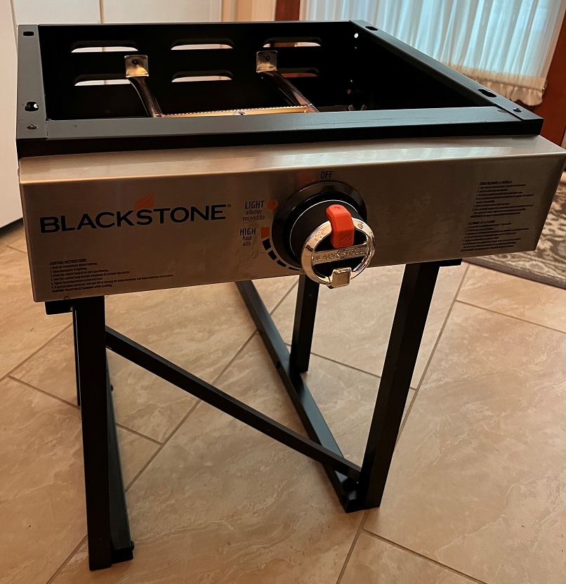
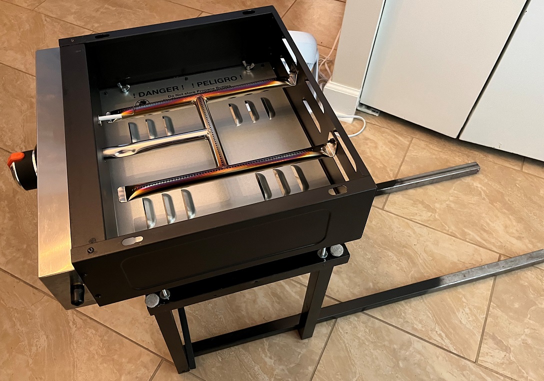
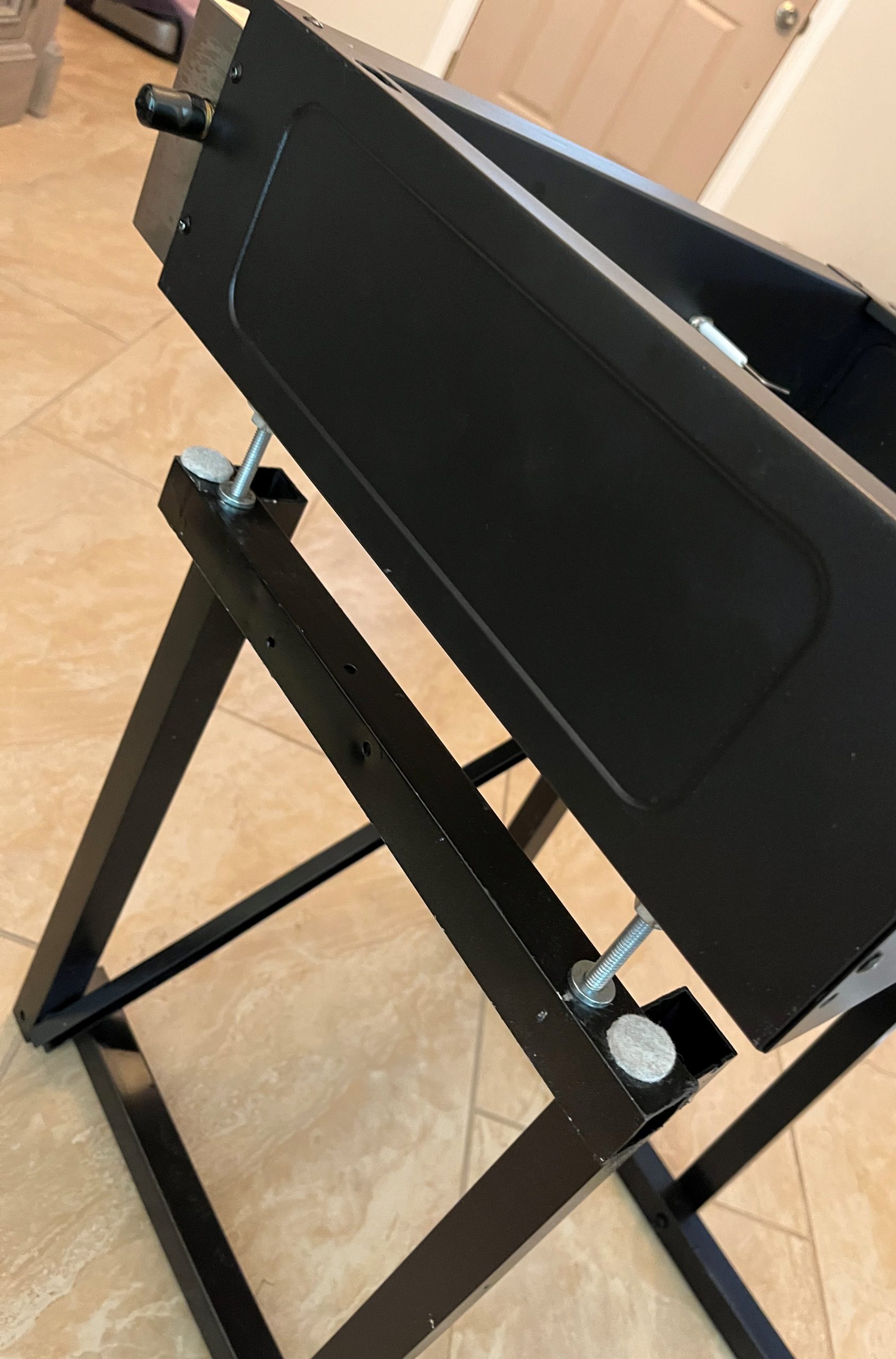
Loosen and adjust anything you feel is not the best fit. Once it is all just right. tighten all the bolts and nuts and secure using super glue, lock-tight or fingernail polish. Apply a final coat of paint to everything. Be sure to spray into the insides of the channel pieces.
Installation:
Slide the two frames into the receivers then set the Blackstone base on top and screw it into the inserts.
Swing the front support into place a push it into the hole in the other side.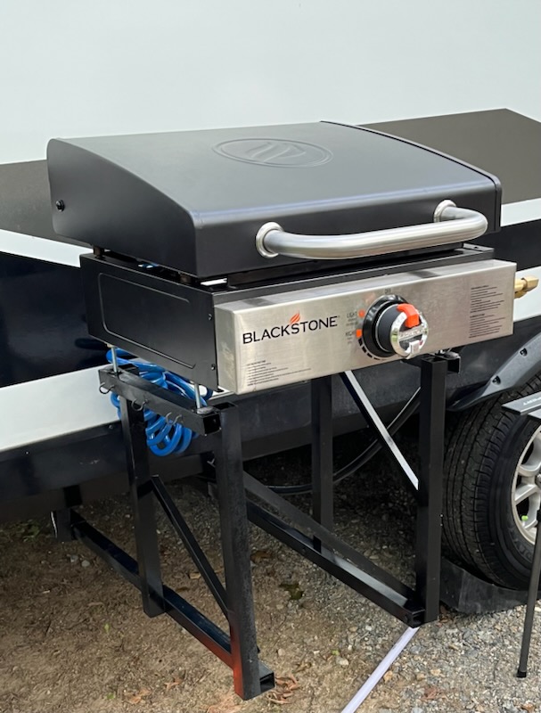
Place the main griddle on top and slide into the locked position.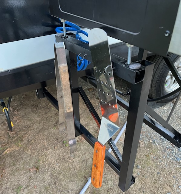
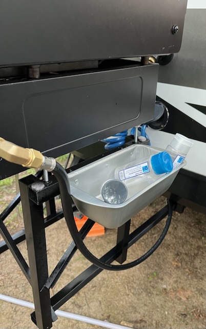
I added hooks to the left side and fashioned a tray for the right side.
A viable option would allow for significant height changes. Simply use the two aluminum channel sizes (one slides into the other) for the vertical pieces of the rack then drill holes and use large cotter pins to adjust the height.
Happy cooking.
